


The right motor drives innovation.
Start your custom motor and inverter design today.
Motor Design & Manufacture
Bespoke or off-the-shelf designs to suit your application
Inverter Design & Manufacture
Cutting edge inverters for all applications and motors
Motor Control Software & Firmware
Patented motor control software built from decades of experience
Technelec has world leading IP for motors, power electronics and software
We specialise in magnet-free motors, sensorless motor control software and next generation motor manufacturing.


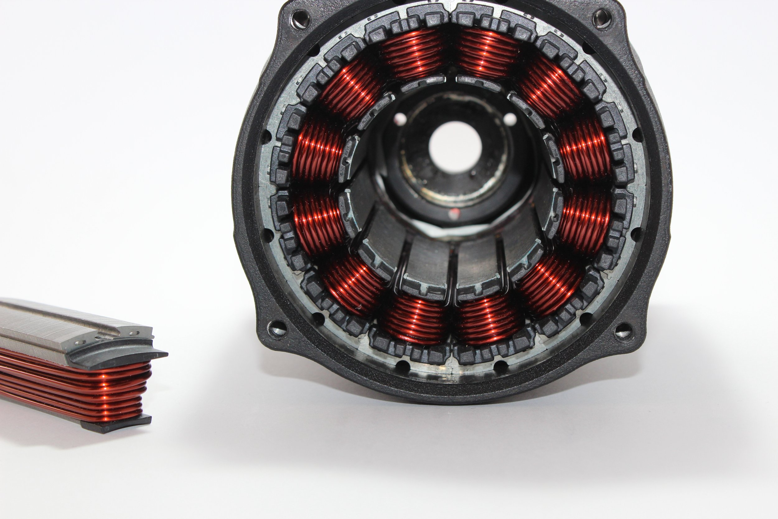

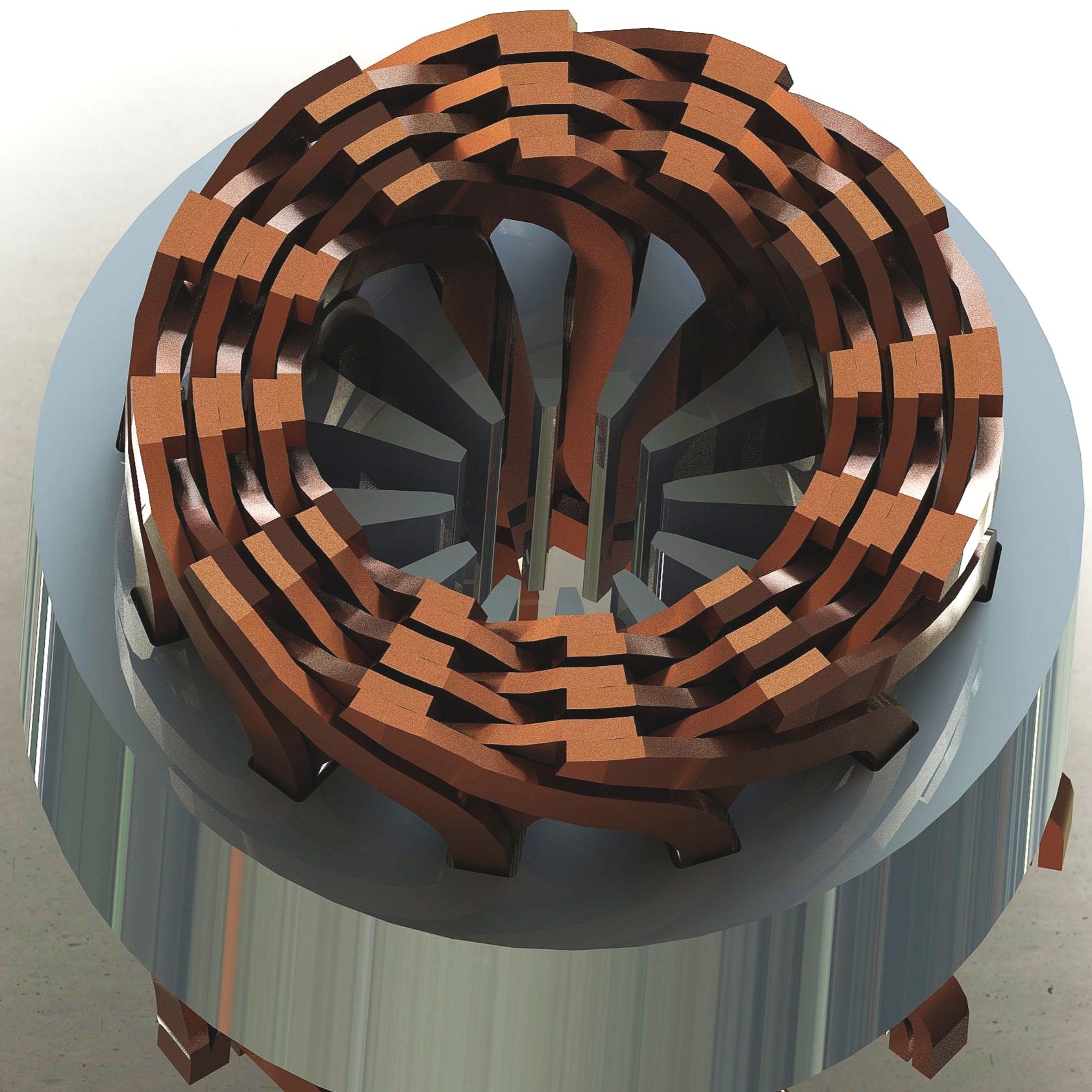
Cutting edge hairpin motor designs.

Traditional Motor Winding
Using wire to wind electrical machines has been used for decades but in large volumes it can create performance variation. Hairpin winding allows a more reliable and repeatable manufacturing process, as well as potential cost savings.